Multi-Measurements Overview
What is a Multi-Measurement
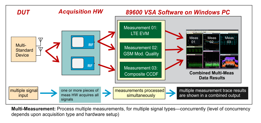
The 89600 VSA extends the traditional one-measurement-at-a-time capability to multiple-measurements-at-a-time. The "Multi-Measurement" feature provides simultaneous signal analysis of multi-standard, multi-format, or multi-carrier signals. Each individual measurement is run concurrently, including input data acquisition and signal processing. All individual measurement trace data results can be shown together "side-by-side" in a combined output.
About Multi-Measurements
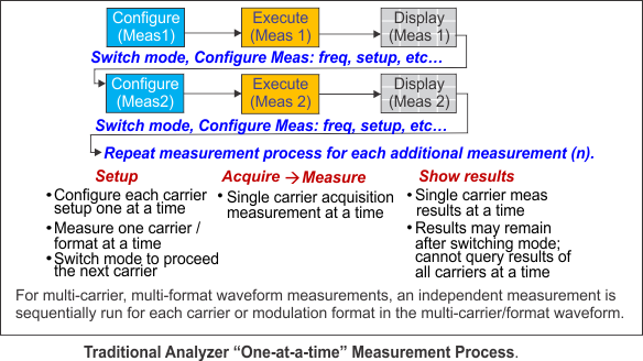
Fundamentally speaking, multi-measurement refers to the ability to process multiple measurements, for diverse signal types--concurrently. The Keysight 89600 VSA software multi-measurement capability is an architectural enhancement that departs from the traditional, "one-at-a-time" measurement approach to a "multiple-at-a-time" measurement approach. Traditional analyzers are limited to single-carrier measurements. A multi-signal measurement requires repeating a set of sequential, independent measurements--one for each signal. The analyzer is set up for the first measurement, the input data is acquired and processed, the output data results shown, the analyzer is switched to the next measurement mode, and these steps are repeated for each measurement. This process is time-intensive and can only provide results for one measurement at-a-time. The measurement results are not time aligned (time synchronous) or simultaneous (phase synchronous), making cross-measurement/time-correlated results impossible to calculate.
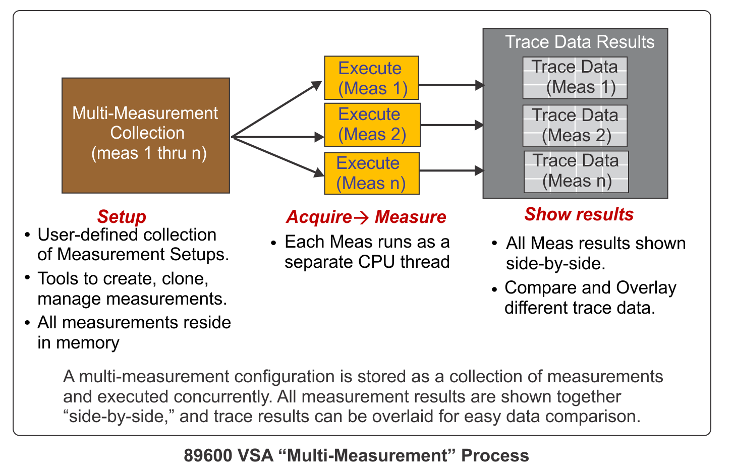
In contrast, the multi-measurement or "multiple-at-time" measurement architecture does allow multiple, independent measurements to run concurrently. The multi-measurement process begins by creating a multi-measurement configuration that contains a collection of the individual measurements. Measurements can then be executed concurrently. All multi-measurement trace results can be output "side-by-side" at the same time. Each measurement includes the same trace data results as if it were a single measurement, plus correlated, cross-measurement results can be calculated with Math Functions or Graph traces. The accuracy of cross-measurement results depends upon the level of concurrency of the acquired time data (see Acquisition Modes).
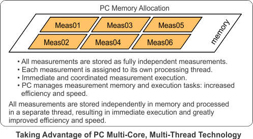
Each measurement resides in memory, independent of the other measurements and these measurements are executed together in parallel. The 89600 VSA software takes advantage of PC multi-core technology by internally assigning each measurement to a separate processing thread. This enables the host PC to manage, execute, and switch between the various measurement tasks providing greatly improved efficiency and speed.
: To learn more about how the multi-measurement feature is implemented, see Multi-Measurement Theory of Operation.
Using Multi-Measurement
Multi-measurements can be configured to meet most multi-measurement test scenarios:
- Analyzer Configurations: user-definable Analyzer Configurations are used to effectively create one wide-bandwidth analyzer from multiple narrow bandwidth analyzers
- Flexible Execution: measurement execution can range from truly simultaneous "time-aligned" execution to user-sequenced measurement execution
- Data Acquisition: measurements can be configured to share or not share the same input data
- Multi-Measurement Size: the number of measurement in the multi-measurement is variable and user-definable.
Analyzer Configurations
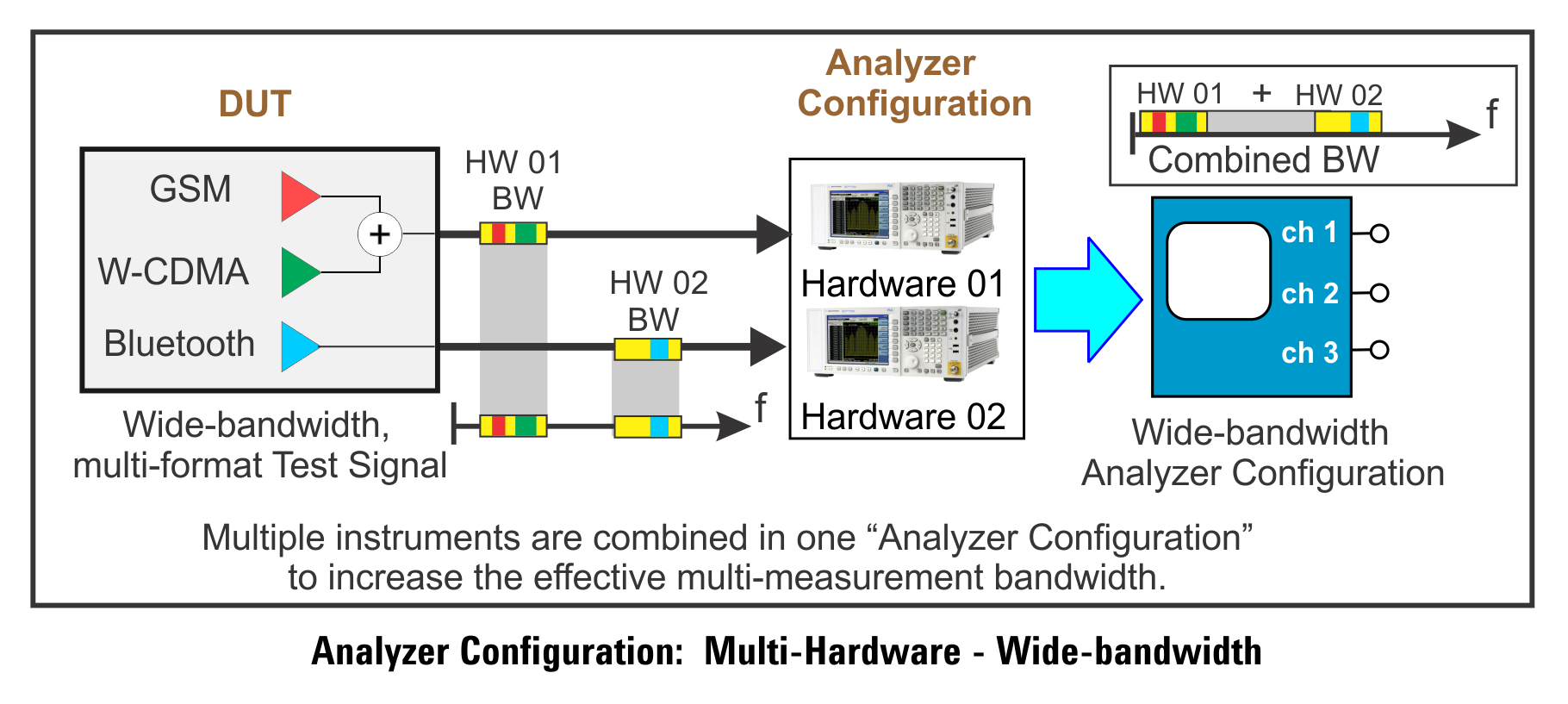
All measurements, including multi-measurements, require an input hardware configuration, called the "Analyzer Configuration." An Analyzer Configuration generally contains a single instrument, but can contain multiple instruments when supported by the hardware. Combining multiple instruments together into a single Analyzer Configuration effectively creates a multi-channel instrument.
With the VSA's multi-measurement and custom channel mapping features, a multi-channel Analyzer Configuration can be used to measure RF Radio Frequency: A generic term for radio-based technologies, operating between the Low Frequency range (30k Hz) and the Extra High Frequency range (300 GHz). signals separated by a wide bandwidth.
For example, the following image illustrates a multi-instrument Analyzer Configuration that can measure a signal whose composite bandwidth is greater than a single instrument's analysis bandwidth.
Acquisition Modes and Concurrency
The Acquisition Mode of the measurements determines how the measurements use the input hardware and input data, and how the measurements are executed or run in a multi-measurement scenario.
With the VSA, you can achieve three different levels of acquisition concurrency:
-
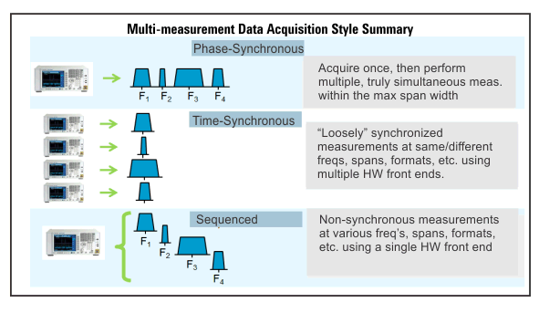
Phase-Synchronous: (AKA Simultaneous) the measurements’ input data has stable phase delta across multiple channels of input hardware or multiple instruments. This also means that the data is time synchronous across channels or instruments.
-
Time-Synchronous: (AKA Time Aligned or “Loose” Synchronization) The measurements’ input data has stable time delta across multiple instruments, but does not have stable phase delta across instruments.
-
Non-Synchronous: The measurements’ input data are acquired at different times with an unpredictable time delta across multiple instruments.
The VSA provides two different Acquisition Modes (along with other settings) that you can use to achieve these levels of concurrency:
- Synchronous: All data acquisition is started at or near the same time, with the goal of achieving Phase-Synchronous or Time-Synchronous acquisition concurrency (depending upon setup), but you can still create a setup which results in a Non-Synchronous acquisition.
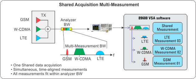
- Phase-Synchronous: Set up multiple measurements to use the same analyzer configuration and enable “Shared” access to the HW. A single (possibly multi-channel) input data acquisition is used to provide data for all of the “Shared” measurements.
- Time-Synchronous: HW triggering is used to align the input data acquisitions between different HW used in multiple measurements. A “primary” measurement (providing a trigger out signal) is connected to the other measurements as an input trigger to loosely align the data from the instruments. You must set up the triggers correctly on all the measurements and you must identify which measurement(s) provide the “primary” trigger (by enabling the “Trig Out” selection). If the triggers are not configured correctly or if no “Trig Out” measurement is selected, then either the multi-measurement will fail to trigger or input data will be Non-Synchronous.
In Phase-Synchronous acquisition mode, each runnable “Shared” group of measurements is grouped together in the Measurements dialog. All other runnable measurements are grouped together in a single “Independent” group.
-
Sequenced: Data acquisitions are potentially started at different times, so only Non-Synchronous acquisitions are possible. Sequenced acquisitions allow you to use the same HW for totally unrelated measurement setups as a separate input data is acquired for each measurement (as opposed to Phase-Synchronous “Shared” measurements which have input and frequency couplings between the measurements).
“Shared” and “Trig Out” selections are not available in Sequenced acquisitions
In Sequenced acquisition mode, all runnable measurements are grouped together in a single “Sequenced” group.
Phase-Synchronous (Shared) Acquisition
Phase-Synchronous acquisitions provide simultaneous fully phase- and time-aligned, multi-measurement data results. Measurements share the same hardware (analyzer configuration) with a single input data acquisition for all measurement that are shared with this hardware. The analyzer configuration maximum span must be wide enough to measure the entire bandwidth of the test signal (analyzer Span > test signal BW).
Time-Synchronous Acquisition
Time-Synchronous acquisitions can make multiple measurements concurrently when you have multiple instruments. Data results are not phase-aligned but external triggering is used to minimize time-alignment deltas between hardware by using the Trig Out feature in the Measurements dialog.
If either “Trig Out” is not enabled or the triggering set up incorrectly, then the resulting acquisition will be Non-Synchronous (i.e. no time relationship between input data acquisitions).
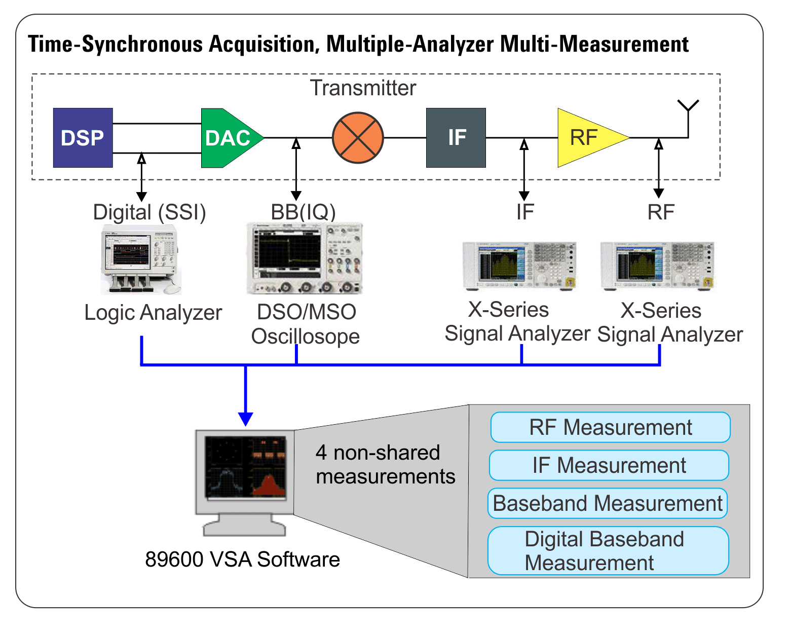
Three example use-cases for the Time-Synchronous acquisitions:
-
: The combined bandwidth of a multi-carrier signal does not fit within the analyzer maximum bandwidth
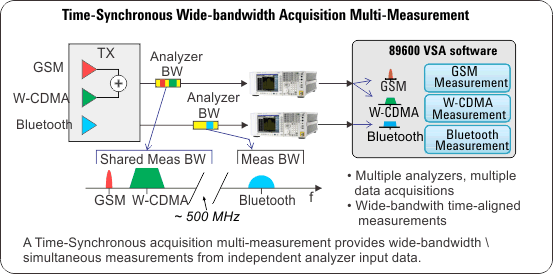
- : The physical separation of the test points prohibit the use of a single analyzer, multiple analyzers are required at each location to measure the signal. For example, one test point could be located inside a building and another test point located outside the building.
-
: The multi-format waveform contains modulation formats that require different measurement hardware types to measure the various formats; e.g. a simultaneous RF radio chain multi-measurement utilizes a logic analyzer, oscilloscope, and signal analyzer.
Sequenced Acquisition
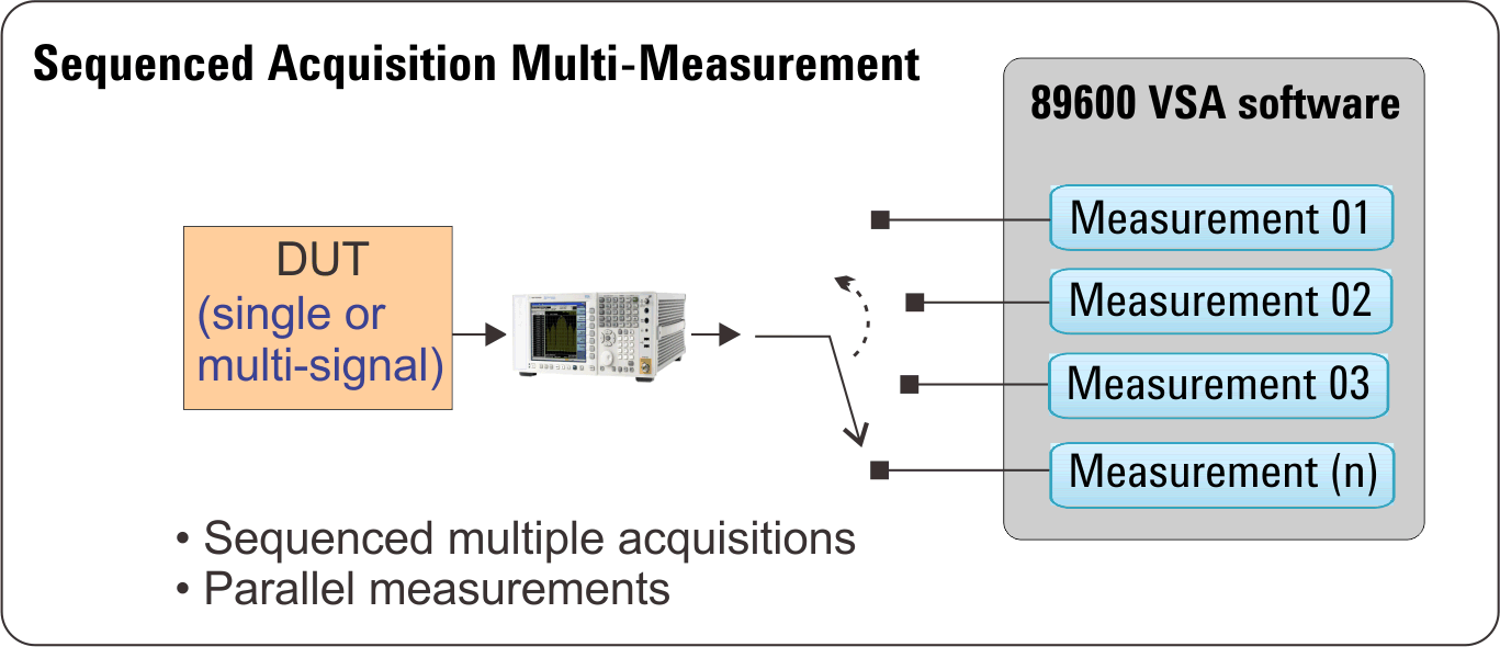
A sequenced acquisition is where a series of measurements are run in sequence. Because all measurement configurations reside in memory, they are ready for immediate execution resulting in decreased switching times. Measurement data are not acquired concurrently, but are acquired automatically in multiple input data acquisitions.
: To learn more about how to use multi-measurement, see the example use cases: About Use Cases.
Acquisition Order
Sequenced measurements acquire data as quickly as possible. All running measurement are internally divided into acquisition groups, where each acquisition group uses the same hardware. Initially, one measurement acquisition is started for the first measurement (lowest measurement index) in each acquisition group. As soon as a measurement acquisition finishes, the next measurement acquisition in the acquisition group is started. This continues until all measurements in all acquisition groups have acquired data. If there are no measurements that use the same hardware, then the affect is that all measurement acquisitions are started at near the same time (in parallel). If all measurements use the same hardware, then the affect is that all measurements acquire data one at a time (in sequence). All measurement acquisitions must finish before any of the measurement calculations are started.
Multi-Channel vs. Multi-Measurement
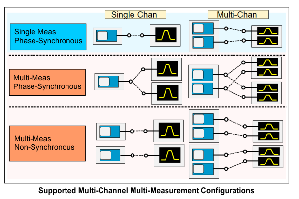
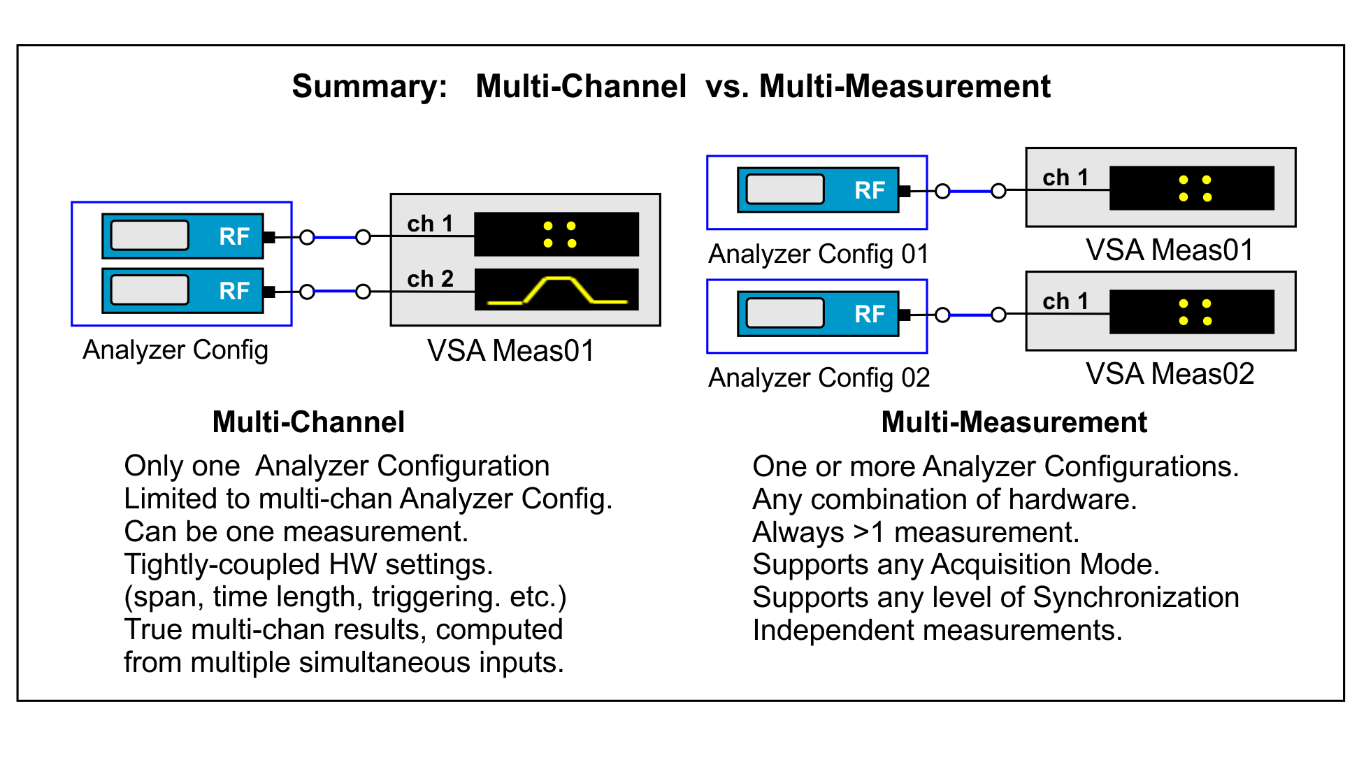
The 89600 VSA supports multi-channel measurements, multi-measurements, and the combination of both: multi-channel multi-measurements.
The fundamental components of a VSA multi-measurement are 1) the input hardware, called the "Analyzer Configuration", and 2) the set of measurements that will be used to create the multi-measurement configuration.
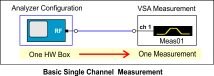
The simplest VSA measurement is a single-channel measurement using an analyzer configuration containing a single instrument.
Multi-channel Measurements
A multi-channel measurement is a single VSA measurement that performs data analysis on a multi-channel signal, for example, an 8-channel MIMO Multiple Input, Multiple Output: A physical layer (PHY) configuration in which both transmitter and receiver use multiple antennas. signal. A multi-channel measurement provides results computed from multiple channels including: ΔTime, ΔPower, I+jQ, MIMO results, etc.
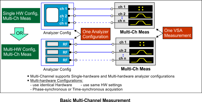
Multi-channel measurements support single and multi-hardware analyzer configurations. Multi-hardware analyzer configurations allow you to combine hardware to expand the input measurement channel capabilities of a single instrument. Even though there are multiple instruments in the analyzer configuration, this is a single analyzer configuration which may provide Phase-Synchronous or only Time-Synchronous multi-channel data depending upon the hardware used in the configuration and the settings of the hardware.
Consult your hardware documentation to determine what conditions this multi-analyzer configuration supports Phase-Synchronous or only Time-Synchronous multi-channel acquisition. Some multi-channel measurements (e.g. MIMO-type demodulation measurements) work correctly with only Time-Synchronous acquisitions.
Multi-hardware analyzer configurations require that:
- all instruments are identical hardware models
- all instruments use the same hardware parameter settings.
Multi-channel measurements only support a single analyzer configuration.
Multi-Measurements
Multi-Measurements can be composed of multiple groups of measurement hardware which support different levels of synchronization, as illustrated below. Multi-channel measurements can only be connected to Multi-channel analyzer configurations.
See Also
Use Cases for Multi-Measurement
Managing Multiple Measurements
